
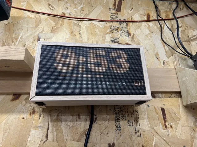
How often do you find yourself juggling multiple time events? When I'm working in the shop I often have multiple irons in the proverbial fire, such as wet paint, glue that needs to set, or even a work-related meeting that I can't lose track of. Like most people, I could track all of this on my phone. But what if the phone isn't easily usable, such as when my hands are dirty? If a task requires too many steps – unlock phone, find Clock app, edit old alarm, spin minute and hour dials, etc – then I probably won't do it; I'll just keep track in my head, which may or may not actually happen.
Enter Timekeeper!
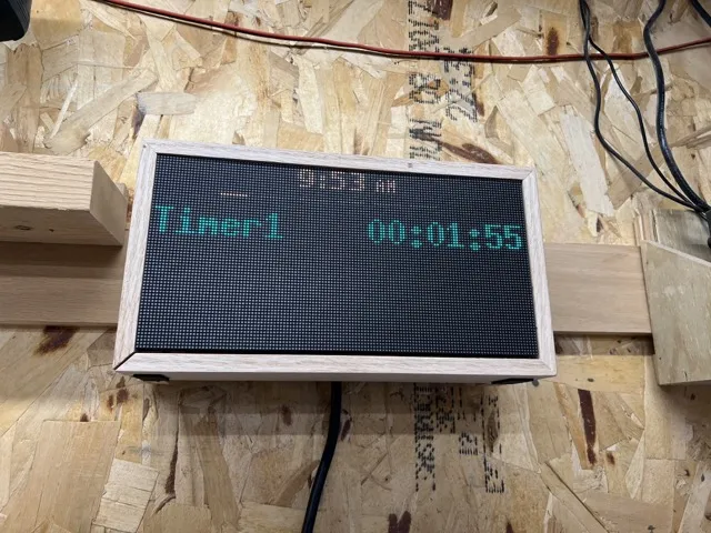
Timekeeper is a clock that responds to your voice commands. From anywhere in the room you can simply say something like "Timekeeper, set an alarm for three hours" and it will display a countdown clock. Need to track another timer? Tell it "Timekeeper, set an alarm for two minutes from now" and it will display both events at the same time. When a time event fires/expires, the piezo buzzer will sound and the expired event will flash on the screen.
Timekeeper can also be controlled via buttons. A 5-button control pad (such as this one) can start/stop/modify timekeeping.
How to Build It?#
Timekeeper is a Raspberry Pi connected to a USB audio device and a P2 LED panel. My Python-based software synchronizes via NTP, displays the time, and listens for audio commands. You can easily build one for yourself for under $100.
I originally coded this for a Raspberry Pi 4 2GB but It will run successfully on a Pi 3A+ as long as you tune your LED panel settings properly. More on that below. Pi's that are lower-powered than this, such as the Pi Zero, will not work.
| None | None |
|---|---|
| Item | Cost |
| Raspberry Pi 3A or better | $25 |
| P2 128*64 LED panel w/ HUB75e cable | $38 |
| 5V 10-amp DC power supply | $12 |
| Geekworm G469 GPIO Terminal Block Breakout Board | $10 |
| Piezo buzzer | $3 |
| USB microphone | $10 |
| TOTAL: | $98 |
You'll need something to house all of the parts in. I built a simple rectangular case from scrap lumber that has notches cut out on the back so that it can hang off the French cleats on my garage wall. You'll also need some wires to connect power supply to the Pi and the LED panel.
Pi-to-LED Panel Wiring#
Connecting the Pi to the LED panel might be the most tedious task of the whole build. My LED panel came with a 16-pin ribbon cable for this purpose, so I cut off one end and attached it to a terminal block breakout board. You can also use DuPont wires and save $10 by avoiding the breakout board, though this can get unruly. Or another option is to use a ready-made HUB75 HAT that plugs onto the Pi's GPIO pins. Regardless of the method you choose, you want to keep the cable lengths as short as possible.
| None | None | None | None | None | None | None |
|---|---|---|---|---|---|---|
| LED Panel Pin # | LED Panel Position | LED Panel Label | Purpose | Raspberry Pi Label | Raspberry Pi Position | Raspberry Pi Pin # |
| 1 | Left, pin 1 | R1 | Red for the top half | GPIO6 | Left, pin 16 | 31 |
| 2 | Right, pin 1 | G1 | Green for the top half | GPIO19 | Left, pin 18 | 35 |
| 3 | Left, pin 2 | B1 | Blue for the top half | GPIO14 | Right, pin 4 | 8 |
| 4 | Right, pin 2 | GND | Ground | GND** | Right, pin 10 | 20 |
| 5 | Left, pin 3 | R2 | Red for the bottom half | GPIO13 | Left, pin 17 | 33 |
| 6 | Right, pin 3 | G2 | Green for the bottom half | GPIO26 | Left, pin 19 | 37 |
| 7 | Left, pin 4 | B2 | Blue for the bottom half | GPIO25 | Right, pin 11 | 22 |
| 8 | Right, pin 4 | E | Row address for 1/32 panels* | GPIO24 | Right, pin 9 | 18 |
| 9 | Left, pin 5 | A | Row address for all panels | GPIO17 | Left, pin 6 | 11 |
| 10 | Right, pin 5 | B | Row address for all panels | GPIO18 | Right, pin 6 | 12 |
| 11 | Left, pin 6 | C | Row address for all panels | GPIO27 | Left, pin 7 | 13 |
| 12 | Right, pin 6 | D | Row address for 1/16 and 1/32 panels* | GPIO22 | Left, pin 8 | 15 |
| 13 | Left, pin 7 | SHIFT | Shift Clock | GPIO11 | Left, pin 12 | 23 |
| 14 | Right, pin 7 | STR | Strobe (also called Latch) | GPIO9 | Left, pin 11 | 21 |
| 15 | Left, pin 8 | OE | Output Enable (active low) | GPIO10 | Left, pin 10 | 19 |
| 16 | Right, pin 8 | GND | Ground | GND** | Right, pin 15 | 30 |
* Not all boards use this pin. If not, it is Ground.
** This particular pin works, but you can use any available GND pin on the Pi.
Power Consideration#
Conveniently enough, this whole project runs on DC 5V electricity. This means you'll need just one power supply and no need to adjust the voltage further. Such power supplies are easy to come by from the usual suppliers (aka Amazon). Never drive a power supply at more than 80% of its rated output power, especially in a circumstances like this where you'll leave it powered on 24x7.
You'll want a power supply with enough oompf to power both the panel and the Pi. A Raspberry Pi 3A+ consumes around 3 amps and the LED panel can consume as much as 5 amps at full brightness, though this can be controlled in the software. Tip: never drive an LED panel at max brightness. A panel driven at 75% brightness is almot indistinguishable from one running at 100%. For this purpose, 60% will be plenty. Pushing an under-powered power supply too hard will resort in screen flickering and unstable activity from the Pi.
Depending on your power supply type, you'll be dealing with wiring that exposes you to high voltages. I shouldn't have to say this, but I will anyway: high voltage electricity is dangerous, so don't do this if you're not sure what you're doing. Get help if you need it.
Software, aka Where the Magic Happens#
Load your Pi with Raspberry Pi OS Lite 64-bit. No need for the GUI. You'll also want to disable the on-board audio, as it interferes with the GPIO signal quality. (FWIW: Raspberry Pi's have notoriously bad audio anyway.) Finally, you'll want to configure it for periodic unattended updates. I won't waste much time on this topic, as you can easily Google all of these steps.
The Timekeeper software itself is available on my Github page:
The installation instructions are also there, but it's pretty straightforward: wget a copy to your Pi, expand the contents, and run the setup.sh script as root. It will install dependencies and configure everything as necessary.
Configuration#
There are numerous options that can be tweaked and tuned via the config.toml file, including:
- LED panel type, resolution, brightness, refresh rate, and bit depth
- Wake phrase (what the clock listens for to accept a command)
- Button control
Note that you'll need to do some minor tweaking to the LED panel settings, as different panels and Pi combinations have their own unique values. This might take a little trial and error. The default settings are for driving a P2 128*64 LED panel on a Raspberry Pi 4.
Conclusion#
This quick project has been a big help to me in my workshop and I plan to deploy another one my office. I might even do one in the kitchen (in a nice looking box, of course) if the wife so desires. Hopefully it'll serve you as well as it serves me.